ERA – RADAR UNIT

ERA - RADAR UNIT

General Descriptions

The radar (Radio Detection and Ranging) system is an electronic device used to detect the presence, direction and speed of a target (aerial, terrestrial or maritime). The radar device is a main component in many systems of navigation, air traffic control, meteorological monitoring, military surveillance, astronomy, etc.

The radar sends a high frequency signal pulses and detects the reflected signal (echo) from a radar target in the detection zone.

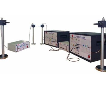
The Radar Unit “ERA” is a radar unit, designed by EDIBON, to study the basic principles about the radar technology.

The ERA unit uses a compact radar which allows students to acquire solid formation about the operation, configuration and installation of a radar system without any previous knowledge. In addition to this, ERA unit allows students to operate and manage a professional radar system.

Students will be able to know different radar concepts such as radar antenna, range and bearing measurement, rain suppressor, sensitivity control, guard zone, etc.

This unit is fully provided with a set of practices, that has to be done at the outdoor, that allow students to understand how works the radar technology and allows the student to learn, in a simple and practical way, the terms and concepts used in radar system such as distance measurements of static and moving objects, operation modes, sensitivity control, suppressing clutters, communication with the GPS module, etc.

The ERA unit consists of different elements: interface unit, radar antenna, GPS module, extendable tripod stands and mobile cart.


Interface unit: It contains the display and the radar control system. The interface unit is the main element of the ERA unit and controls and shows the information provided by the outdoor devices: the radar antenna and the GPS module. It contains the display unit that shows all the navigation data and the radar PPI (Plan Position Indicator). The display unit also includes the buttons to configure the many options of the radar system (setting alarms, sensitivity adjustment, suppressing the clutter, etc). The interface unit includes a battery with a battery charger to facilitate the outdoor operation of the unit. The interface unit also includes two indicator led to show the battery status and the connectors to the GPS module and the radar antenna in the front panel. Radar Antenna: It contains the directional antenna, the microwave generator and the microwave receiver. The directional antenna can rotate to scan the horizontal plane. It also includes a connection cable to the interface unit, with approximately10 m. of long, which allows the users to place the radar antenna at safe distance from the interface unit. The radar antenna is mounted on an extendable tripod stand which hold the antenna at an appropriate height. The radar antenna has to be placed at outside of the laboratory in a large and open area. GPS module: It is a device that shows the current location, altitude, speed and UTC time information anywhere on the earth using the Global Positioning System (GPS). The GPS module includes a cable to connect to the interface unit, for power supply of the GPS module and communicating with the display unit. Extendable tripod stands: Extendable tripod stand to hold the radar antenna at appropriate height. The tripod stand contains a bull’s eyelevel for the radar antenna leveling in uneven grounds. Mobile cart: It is a mobile structure to hold the elements of the ERA unit. It allows user to operate with the ERA unit at the outdoor. The mobile cart incorporates wheels (strong tires) to facilitate its mobility and the operation in uneven grounds.

GUIDED PRACTICAL EXERCISES INCLUDED IN THE MANUAL

  1. Familiarization with the unit.
  2. Establish communication with GPS module.
  3. Configuration of the radar range.
  4. Sensitivity adjustment.
  5. Range measurement.
  6. Bearing measurement.
  7. Setting of the suppressing interference function.
  8. Setting of the suppressing rain clutter function.
  9. Analysis of the guard alarm function and establish a guard zone.
  10. Analysis of the watchman function.

Product Information PDF

ERA - RADAR UNIT Brochure

EGPS – GPS TRAINER

EGPS - GPS TRAINER

General Descriptions

The EGPS unit is the GPS trainer designed by EDIBON to study the basic concepts about global positioning. This unit allows to acquire solid formation about the operation mode of a GPS receiver without any previous knowledge.

The EGPS unit allows the student to learn, in a simple and practical way, the basic terms and concepts used in global positioning systems such as trilateration, GPS starting modes, geographic Azimuth, etc.

GUIDED PRACTICAL EXERCISES INCLUDED IN THE MANUAL

  1. Study the operation principle of a GPS receiver.
  2. Determination of the GPS state.
  3. Configuration of the communication parameters.
  4. Study of the signal-to-noise ratio (SNR).
  5. Study of NMEA sentences.
  6. Study of geographic Azimuth.
  7. Basic concepts about navigation.
  8. Measurement of longitude, latitude and altitude.
  9. Study of the time.
  10. Study of the DOP effect.
  11. Advanced concepts about the GPS receiver.

Product Information PDF

EGPS - GPS TRAINER brochure

EANC – COMPUTER CONTROLLED ANTENNA UNIT

EANC - COMPUTER CONTROLLED ANTENNA UNIT

General Descriptions

The Computer Controlled Antenna Unit, “EANC”, is an advanced system that operates in conjunction with a computer (PC), which allows the control and data acquisition of the antenna measurement by means the SCADA System (control interface box + control software).

The “EANC” performs the full-automatic 360° rotation of the transmitter antenna tower, controlled by the software, for draw the antenna radiation pattern and display it in the computer (PC) window.

The “EANC” also allows the full automatic frequency sweep in order to perform the bandwidth analysis of an antenna.

The “EANC” allows students to learn how to perform the essential antenna measurements: radiation pattern with the measure of the azimuth and elevation plots (electrical and magnetic planes), real time signal level, standing wave ratio (SWR), study the effectiveness of antenna through a wide range of frequencies (bandwidth), directivity and antenna’s power gain. All of these measures are displayed in the computer (PC), and the student can save the results for subsequent analysis.

This Computer Controlled Unit is supplied with the EDIBON Computer Control System (SCADA), and includes: The unit itself + a Control Interface Box + a Data Acquisition Board + Computer Control, Data Acquisition and Data Management Software Packages, for controlling the process and all parameters involved in the process.

GUIDED PRACTICAL EXERCISES INCLUDED IN THE MANUAL

  1. Familiarization with the unit.
  2. Installation, connection and familiarization with the computer control software.
  3. Basic principles of radiation pattern parameters measurement.
  4. Study of the surrounding signals.
  5. Distance effect over radiation power.
  6. Direction of maximum radiation and gain of an antenna.
  7. Analysis of the antenna bandwidth.
  8. Study of monopole antennas.
  9. Study of antennas with ground planes.
  10. Study of dipole antennas.
  11. Study of loop antennas (circular, square and diamond loop antennas).
  12. Study of circular polarization helical antennas.
  13. Study of Yagi-Uda antennas.
  14. Study of microstrip patch antennas.
  15. SWR measurement and conversion in Return loss and Reflected Power.
  16. Improvement of the performance of a system.


Product Information PDF

EANC – COMPUTER CONTROLLED ANTENNA UNIT

ESA-Satellite Trainer

General Descriptions

The “ESA” trainer is an advanced system that operates in conjunction with a computer (PC), which allows students an easy way to manage and visualize the data. The “ESA” software allows to perform multiple actions: configuring the sending data, selecting the desired test point to visualize, selecting different faults in the equipment, etc.

The “ESA” trainer is divided into different modules to allow the student a better understanding of the unit. These modules are: Satellite Ground Transmitter Station, Satellite Ground Receiver Station, Satellite Repeater and the Control Signal and Data Acquisition Module.

The Satellite Ground Transmitter Station works as a real ground based equipment, transmitting the signal (Uplink) to the Satellite Repeater through the Satellite Ground Transmitter Antenna. The Satellite Ground Receiver Station works as a real ground based equipment, receiving the signal (Downlink) from the Satellite Repeater through the Satellite Ground Receiver Antenna. Both, Transmitter and Receiver, are connected to the computer for signal analysis, configuring the data transmission, data visualization, etc.

The Satellite Repeater Module works as real active satellite repeater. It includes a processing system that amplifies the incoming signal from the Satellite Ground Transmitter Station (Uplink) through the Satellite Receiver Antenna, and emits the processed signal in a different band of frequencies (Downlink) through the Satellite Transmitter Antenna.

GUIDED PRACTICAL EXERCISES INCLUDED IN THE MANUAL

  1. Study of the operation principles of a satellite communication system.
  2. Basic principles of analog modulation, frequency modulation (FM).
  3. Basic principles of analog demodulation, frequency modulation (FM).
  4. Basic principles of digital modulation, differential quadrature phase shift keying (DQPSK).
  5. Basic principles of digital demodulation, differential quadrature phase shift keying (DQPSK).
  6. Study of the characteristics of the Satellite Ground Transmitter Station, Satellite Repeater and Satellite Ground Receiver Station.
  7. Study of the communication system through a Satellite Repeater performing the uplink and downlink.
  8. Performing data transfers through a satellite communication system (Satellite Ground Transmitter Station–Satellite Repeater- Satellite Ground Receiver Station).
  9. Study of the quality of the data transmission link.
  10. Analysis of the system response with different fault insertions in the Satellite Ground Transmitter Station.
  11. Analysis of the system response with different fault insertions in the Satellite Repeater.
  12. Analysis of the system response with different fault insertions in the Satellite Ground Receiver Station.

Product Information PDF

ESA-Satellite Trainer